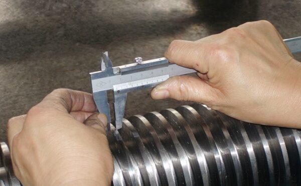
When you measure the screws, we basically need any information required to
manufacture a set. Try to find areas on the screws that do not have excessive wear to measure the
outside diameter. The very beginning of Zone 1 and the Vent Zone are good areas to check. The
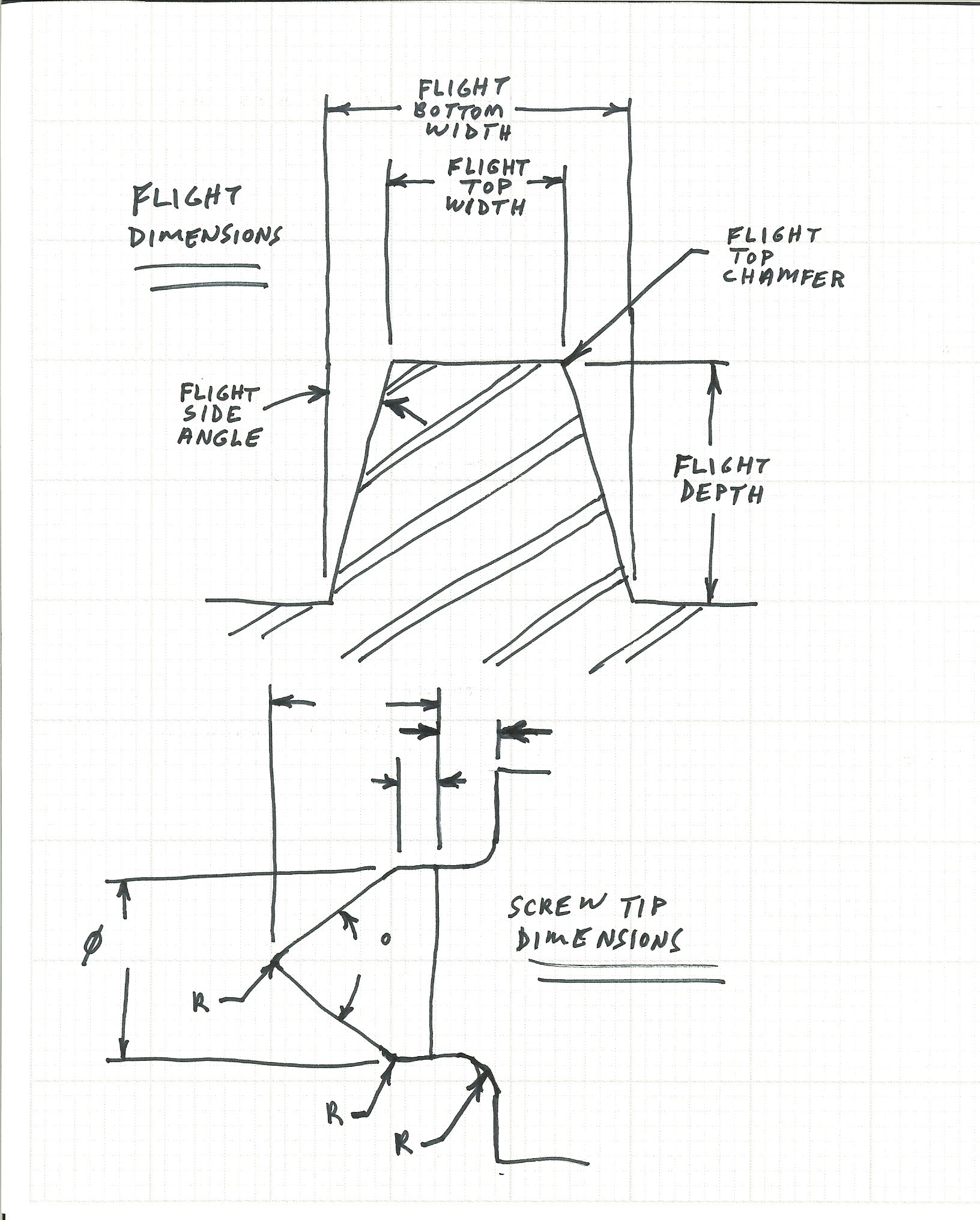
centerline distance can be checked on the barrel if we do not have it already. All of the flight dimension should be measured parallel to the screw centerline, for consistency.
You can use the following chart to record the flight information in the different zones. Also, you should make sketches and measurements of the screw tips, screw shafts (i.e. spline type, size, and length; shaft diameters and lengths; hole sizes and locations…), and any parts you can remove. Typically, the screws are built to metric dimensions, so it is better if you can measure in mm, but we can work with inch dimensions too.
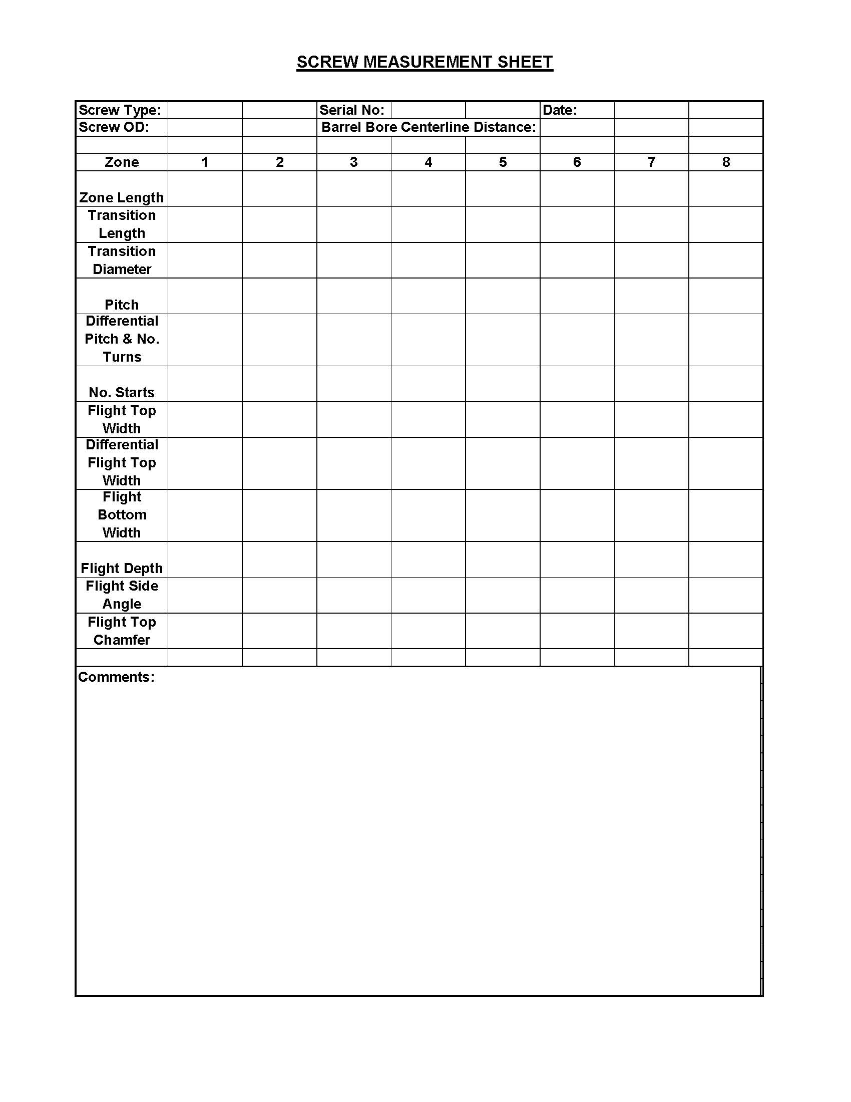
Screw Flight Measurements:
- Zone Length – Measure each zone individually. As a double-check, it is good to make an overall
length measurement of the flighted section of the screw and note it in the comments section. - Transition Length – If there is a transition groove between zones, measure its width.
- Transition Diameter – Measure the root diameter of the Transition groove.
- Pitch – Measure pitch parallels to screw centerline, through one turn (i.e. if there are 3 starts,
measure across 3 flights). - Differential Pitch & No. Turns – Check zones for a differential pitch at the beginning or end of the
zone, that thins out the flights and note the beginning or end of the zone and the leading or trailing face of flights. Typically, differential pitches run 1/2 or 1 turn. - No. Starts – Count the number of the flight that starts in the zone.
- Flight Top Width – Measure the flight top width parallel to the screw centerline. If flights are chamfered, try to estimate width without chamfer.
- Differential Flight Top Width – If flights have a differential pitch, measure the flight top width at the end of the zone.
- Flight Bottom Width – Measure flight bottom width parallel to screw centerline, but not including
radius at root diameter. - Flight Depth – Measure from OD to Root Diameter. If excessive wear on OD, add half of the amount below nominal OD dimension.
- Flight Side Angle – Measure the flight side angle parallel to the screw centerline. Typically these are in 5-degree increments.
- Flight Top Chamfer – Note the size and angle of any chamfers on top corners of flights.
- Comments – Note any kneading cutouts (location, width/radius, depth, number of rows around
the circumference, number of cutouts per row, the total number of cutouts per screw, and if the rows are parallel to the screw centerline or at an angle (estimate angle). Note areas covered by chrome. Note any other characteristics, such as a mixing head consisting of mixing pins and their relevant dimensions.
Barrel Measurements:
For the barrel, again, try to make sketches and make any measurements that would be necessary to manufacture one. We need bore diameters, centerline distance, length, outside diameters, mounting flats, hole sizes and locations, bolt hole sizes and patterns, thermocouple hole locations, and flange dimensions.
It is good if you can take many digital pictures of the screws and barrel from different angles, some close-up, and some of larger areas. This gives us a reference to look at if we have questions.
For more questions, please contact us at sales@britechintl.com.

